How to Choose an Electronic Load for Your Bench
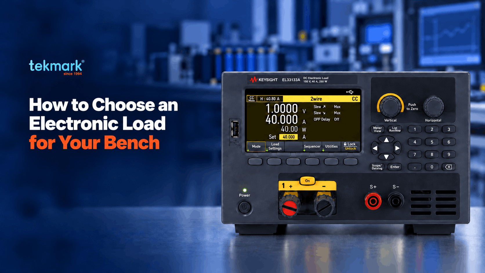
An electronic load is a versatile, programmable instrument designed to sink controlled current, hold specified voltages, emulate precise resistance, or absorb constant power from a device under test (DUT).
Unlike static resistive loads, selecting the right electronic load depends on matching core specifications such as operating limits, dynamic transient speed, and minimum voltage capabilities to your exact source requirements rather than relying on headline wattage alone.
This practical guide highlights what a DC electronic load accomplishes over traditional resistor banks, details its four primary operating modes (CC, CV, CR, and CP), outlines key performance specifications, and explores how Keysight’s EL30000 Series bench electronic loads meet real-world power testing challenges.
Insights and technical details are referenced directly from Keysight specifications and application notes.
Key Takeaways
- Choosing an electronic load means matching its modes and specifications to your source, not buying on wattage alone.
- A load actively sinks power and measures while it loads, which a fixed resistor bank cannot do, per Keysight’s Electronic Load Fundamentals white paper.
- Electronic load has 4 operating modes: constant current, constant voltage, constant resistance, and constant power. Each suits a different test.
- The deciding specs are the voltage, current, and power envelope, the minimum operating voltage, and the slew rate.
- Keysight’s EL30000 bench range covers three models from 250 W to 600 W, all rated to 150 V, with modular N3300 and regenerative EL4900 loads for production lines.
What Does An Electronic Load Do?
An electronic load draws a controlled amount of power from a device under test (DUT), such as a power supply, battery, DC-DC converter, solar panel or LED driver. It allows engineers to apply precise load conditions and measure how the DUT performs under both steady-state and changing power demands.
Unlike a fixed resistor, a programmable electronic load can maintain a selected operating mode—constant current (CC), constant voltage (CV), constant resistance (CR) or constant power (CP)—even as the DUT’s output changes. It can also generate dynamic load steps to simulate real-world changes in power demand.
Engineers use electronic loads to:
Test power-supply regulation and transient response
Verify current limiting and protection functions
Measure battery discharge capacity and energy
Evaluate DC-DC converter performance and efficiency
Reproduce changing load profiles during product validation
In simple terms, a DC power supply provides power to a DUT, while an electronic load absorbs power from the DUT under controlled test conditions.
Technical reference: Keysight Electronic Load Fundamentals
What are the four operating modes, and when does each matter?
Electronic loads operate across four primary modes: constant current (CC), constant voltage (CV), constant resistance (CR), and constant power (CP). Each mode maintains one variable while allowing others to adjust dynamically based on the source behavior.
- Constant Current (CC): The load regulates current draw at a fixed level regardless of voltage changes. Ideal for testing power supply load regulation and current-limit circuits.
- Constant Voltage (CV): The load adjusts current draw to maintain a specified voltage across its terminals. Essential for evaluating current-source devices, solar cells, and LED drivers.
- Constant Resistance (CR): The load emulates a precise linear resistance value, scaling current linearly with voltage changes. Perfect for replacing bulk resistor banks and testing start-up load profiles.
- Constant Power (CP): The load holds power consumption constant by increasing current draw as voltage decreases. Highly effective for testing battery capacity, energy storage devices, and DC-DC converters under constant watt loads.
These operational modes reflect design guidelines from Keysight’s DC electronic load portfolio. Determine the required mode for your test application, then verify the right model support it.
Which Specifications Determine The Right Electronic Load?
Four specifications decide the choice: the voltage, current, and power envelope, the minimum operating voltage, the slew rate, and the built-in measurement and control. Match each to your source, then confirm the model against Keysight’s datasheet.
(A) Voltage, current, and power envelope
The electronic load must accommodate your DUT’s maximum voltage, current, and power simultaneously across its operational curve. Crucially, a load cannot pull its maximum current at maximum voltage if that combination exceeds its total power rating.
For example, the Keysight EL34143A is rated for 150 V, 60 A, and 350 W. Its full 60 A current draw is available up to approximately 5.8 V (350 W ÷ 60 A = 5.83 V).
Beyond this point, the instrument limits current to remain within its 350 W power boundary. Always evaluate your source’s worst-case operating point rather than relying on individual maximum ratings.
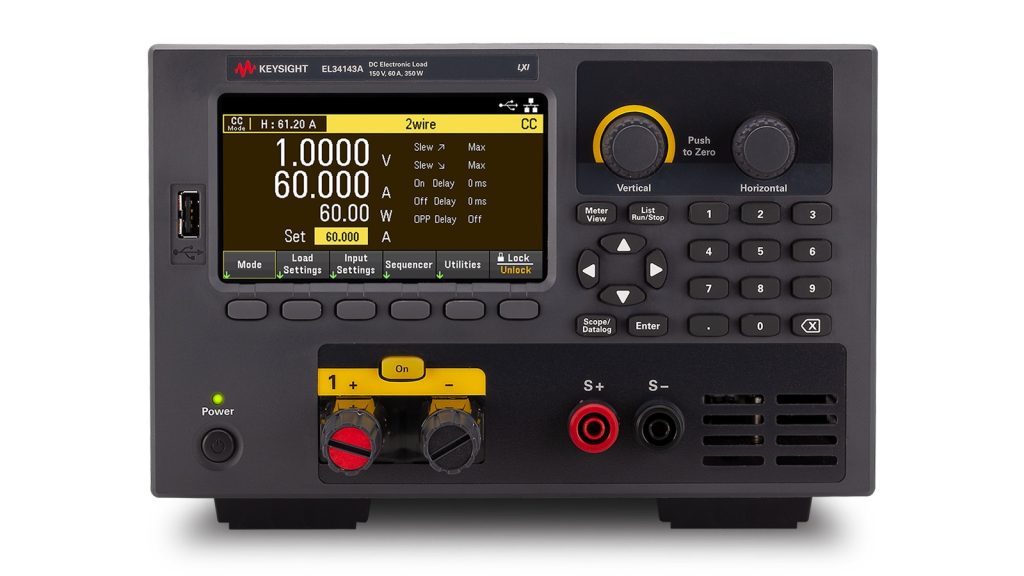
Keysight EL34143A
(B) Minimum operating voltage
Minimum operating voltage (Vmin) is the lowest terminal voltage required for the load to sink its full rated current. Below Vmin, internal MOSFETs cannot conduct fully, limiting maximum current draw.
According to the EL30000 Series data sheet, high-range inputs require approximately 1.5 V at full current, whereas low-range operation operates down to 0.15 V.
Evaluating low-voltage sources, such as a single 1.2 V fuel cell or sub-volt point-of-load (POL) regulator, requires selecting a low-voltage range or dedicated low-Vmin load.
(C) Slew rate
Slew rate dictates how quickly the load can change current (A/s or A/µs), determining its ability to emulate fast transient load spikes. High-speed microprocessors transitioning from sleep to full load in microseconds demand fast slew rates to evaluate power supply transient recovery times accurately.
The Keysight EL34143A provides configurable slew rates ranging from 40 kA/s up to 4.8 MA/s across its ranges.
Higher speed settings offer rapid dynamic response, while lower settings optimize low-current resolution. Align the instrument’s slew rate capabilities with your DUT’s fastest load edge.
(D) Measurement and control
Integrated measurement tools—such as built-in scope views and data loggers—streamline bench setups by reducing the need for external meters.
The Keysight EL30000 Series captures voltage and current using an integrated 200 kHz oscilloscope mode with up to 256k sample depth. It also features a real-time data logger with sample intervals from 20 microseconds to 60 seconds, alongside List mode for complex automated sequencing.
Standard USB and LAN (LXI) connectivity ensures seamless integration into automated test environments and remote bench automation setups.
For assistance in selecting the right electronic load, share your DUT’s voltage, current, power and test requirements with Tekmark’s engineering team for a suitable configuration recommendation.
Read more: A supply’s recovery after a load step is measured on the scope. Our guide on how to choose the right oscilloscope for your engineering work covers the bandwidth, sample-rate, and channel decisions.
Common Electronic Load Applications
DC electronic loads excel across three primary applications: power supply regulation and transient testing, battery discharge and capacity testing, and DC-DC converter validation. Each application leverages distinct modes and instrument capabilities.
(i) Power supply load-regulation and transient testing
In CC mode, the load can apply defined current levels to measure load regulation, verify current limiting and generate light-load-to-full-load transitions. For example, a 5 V, 20 A supply delivers 100 W and fits within the power rating of a 250 W EL33133A, provided all operating-region and transient requirements are also satisfied.
For transient-response testing, the electronic load generates the load step while an oscilloscope measures the supply output deviation and recovery. Slew rate, step amplitude, duty cycle, wiring and probing method all affect the result.
Keysight frames this as checking load regulation and transient response, measured on the supply output with your Keysight oscilloscope while the load provides the step.
(ii) Battery Discharge and Capacity Testing
An electronic load can discharge a battery under controlled conditions while measuring voltage, current, power, capacity and energy over time. The appropriate mode depends on the intended test rather than on one universal rule.
• Use CC mode for controlled discharge-current and capacity tests when the method or battery specification defines a constant current.
• Use CP mode when the battery powers equipment that behaves approximately like a constant-power load through a regulated converter.
• Use CR mode when a predominantly resistive load is the more representative condition.
• Use List or dynamic operation when the objective is to reproduce a changing device-load profile.
The EL30000 Battery Test function provides configurable cut-off conditions based on voltage, capacity or elapsed time. These conditions help prevent over-discharge while allowing the instrument to record the discharge profile. Multi-cell systems may also require additional temperature and cell-voltage monitoring beyond the electronic load’s own input measurements.
An integrated data logger records discharge curves over time. For multi-cell or long-term battery burn-in tests, combining loads with a dedicated data acquisition system expands channel capacity and logging flexibility.
(iii) DC-DC converter validation
A programmable electronic load can test converter regulation, efficiency, transient response, start-up behaviour and protection functions across multiple load levels. List mode can apply a sequence from light load to rated load, while the selected slew rate controls the transition between current levels. Efficiency testing also requires accurate input-side measurements; the load measurement alone does not provide the converter’s complete input-to-output efficiency.
Comparison of Keysight EL3000 Series Bench Models
The Keysight EL30000 Series comprises three benchtop configurations rated up to 150 V, each equipped with all four operating modes and advanced measurement features.
| Model | Inputs | Max voltage | Max current | Power | Modes | Notable |
| Keysight EL33133A | 1 | 150 V | 40 A | 250 W | CC, CV, CR, CP | Scope mode, datalogger |
| Keysight EL34143A | 1 | 150 V | 60 A | 350 W | CC, CV, CR, CP | 40 kA/s to 4.8 MA/s slew, List mode |
| Keysight EL34243A | 2 | 150 V | 60 A per input | 600 W total (300 W per input) |
CC, CV, CR, CP | Dual input for two rails |
All three models feature CC, CV, CR, and CP modes, a 1.5 V Vmin rating on high range, 200 kHz scope mode, and built-in data logging, as detailed in the EL30000 Series data sheet. Model selection depends primarily on power rating, current capacity, and channel count.
The single-input EL33133A (250 W) suits general low-power supply and component testing. The EL34143A (350 W) delivers higher current headroom and faster 4.8 MA/s slew rates for dynamic transients.
The dual-input EL34243A enables simultaneous testing of two independent power rails or devices from a single benchtop unit.
When to Consider Modular or Regenerative Electronic Loads
N3300 Series for Configurable Automated Test
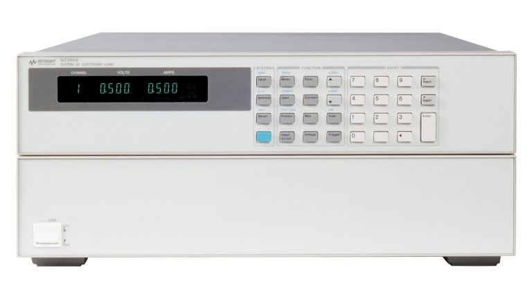
When an automated system requires more channels or a configurable rack solution, the Keysight N3300 Series provides user-installable load modules. The N3300A mainframe offers six slots and up to 1,800 W total, while the N3301A offers two slots and up to 600 W.
Individual modules range from 150 W to 600 W. For example, the N3306A is rated at 600 W, 60 V and 120 A. Module width and total mainframe capacity determine how many modules can be installed. The N3300 modules provide constant-current, constant-voltage and constant-resistance programming; do not assume they provide every EL30000 operating mode or feature.
Keysight N3300A
EL4900 Series for Higher Power and Energy Regeneration
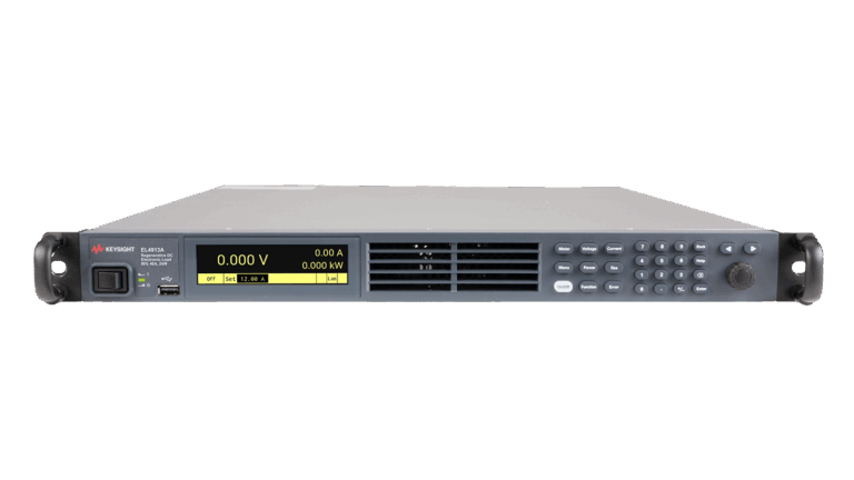
For higher-power testing, the Keysight EL4900 regenerative DC electronic loads cover individual power levels from 2 kW to 12 kW and can be paralleled for greater capacity. Instead of dissipating all absorbed energy as heat, they return energy to the local AC grid, reducing facility power consumption and cooling requirements.
The EL4913A is rated at 80 V, 40 A and 2 kW in a compact 1U format. Keysight positions it for testing energy-storage systems, power converters and other higher-power devices. Facility, grid-connection, safety and integration requirements should be reviewed before selecting a regenerative system.
Keysight EL4913A
Read more: A full test bench often pairs the load with RF instruments. Our guide on RF testing explains what radio frequency measurement covers.
Electronic Load Selection Checklist
Review these key parameters before selecting an electronic load. Guidance is drawn from Keysight’s Electronic Load Fundamentals white paper and the EL30000 Series data sheet.
| What to confirm | Why it matters | How to specify it |
| Voltage, current, and power ceiling | The load must cover your source on all three interacting limits | Give your source’s maximum V, A, and W; pick a load that clears all three (Electronic Load Fundamentals) |
| Minimum operating voltage | A low-voltage cell or fuel cell cannot drive full current into a load that needs volts to conduct | Give your lowest test voltage; confirm the load sinks your current there (EL30000 data sheet) |
| Operating mode | Each test needs its own mode | Match the mode to the job, such as CP for battery drain or CC for supply testing (Keysight mode guidance) |
| Slew rate | Emulating a fast load step needs adequate slew rate | Give your fastest load step; confirm the slew rate covers it (EL30000 data sheet) |
| Measurement and logging | Built-in capture can remove a separate instrument | Decide if you need capture; EL30000 scope mode and datalogger may cover it |
| Inputs and rack density | Multi-rail and production lines need channels and rack space | Count your rails and lines; a dual-input EL34243A or modular N3300 may fit (general practice) |
This table covers the load itself. Power supply and source measure unit specs are a separate decision.
Conclusion
Choosing an electronic load is an operating-region and application-matching exercise. Start with the DUT’s actual voltage-current points and test method, then check minimum operating voltage, operating mode, slew rate, measurements, channel count and connectivity. Do not select a model from wattage alone.
For many benchtop power-source tests, the Keysight EL30000 Series combines programmable loading, measurement, waveform capture and data logging in a compact instrument. For greater channel density or higher power, consider the modular N3300 Series or regenerative EL4900 Series according to their individual capabilities.
Why Tekmark?
Tekmark is the authorized Keysight distributor with strategic coverage across Southeast Asia, operating through direct offices in Malaysia, Singapore, and the Philippines.
· Over 30 years of expertise in electronic test and measurement solutions.
· Established presence across Southeast Asia, supporting customers through an extensive regional network.
· In-house R&D engineering expertise for application support and system integration.
· Value-added services, including calibration, professional training, and technical consultation.
· Dedicated local technical support before, during, and after your purchase.
FAQs
An electronic load tests power sources by drawing a controlled current, voltage, resistance, or power from them. Engineers use it to check power supply regulation, characterise battery discharge, and validate DC-DC converters. It holds a test point steady and measures the source while it loads.
A DC power supply sources voltage and current into a device, whereas an electronic load sinks energy from a power source. Source measure units (SMUs) combine sourcing and sinking capabilities in a single instrument. Electronic loads specifically measure how power sources behave under precise dynamic load conditions.
The four modes are constant current (CC), constant voltage (CV), constant resistance (CR), and constant power (CP). Each holds one quantity steady while the others follow. Keysight maps CC to power-consumption testing, CV to a current source, CR to replacing a resistor, and CP to storage capacity.
Constant power (CP) mode suits battery discharge testing. It holds power steady and raises current as the cell voltage falls, which matches how a device drains a pack. The EL30000 datalogger records voltage, current, and energy across the run.
The main specifications are the voltage, current, and power envelope, the minimum operating voltage, and the slew rate. The envelope must cover your source on all three limits. Minimum operating voltage matters for low-voltage cells, and slew rate sets whether the load can emulate fast transients.
Not in every case. Built-in Scope View can capture the load’s voltage and current, but an external oscilloscope may still be required for higher-bandwidth DUT-output measurements, multi-node probing and advanced triggering.
Related Articles