Need the Right Setup for Accurate Power Supply Ripple Measurements?
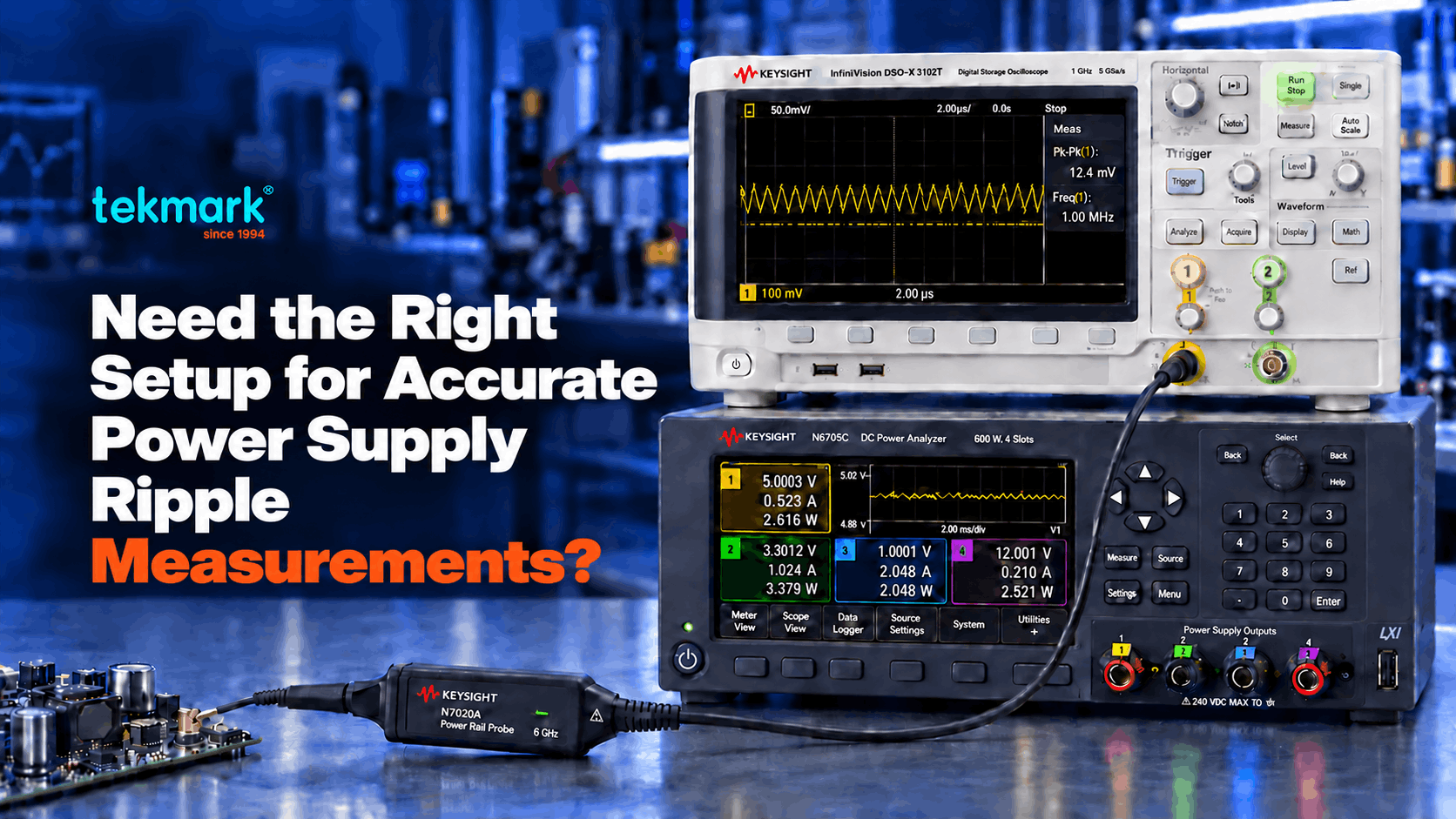
A power supply ripple measurement can be distorted by the probe connection, the oscilloscope settings and electrical noise around the bench. The waveform on screen may differ from the ripple and noise actually present on the DC rail.
Engineers often clip a 10:1 passive probe to a Keysight oscilloscope, read the ripple and take it as the signal. Probe attenuation, ground-loop pickup and the wrong settings can make that trace look larger, smaller or noisier than it is.
This guide compares three ways to probe a DC rail. It covers the scope settings that change the result, and the probe and scope pairings that make millivolt ripple readable. It does not rule out the supply, which still has to be checked.
Key Takeaways
- Ripple readings are shaped by probe attenuation, grounding, scope noise, bandwidth and stray pickup, so check the setup first.
- A 10:1 passive probe attenuates millivolt ripple toward the noise floor of the measurement system.
- A direct 50 ohm scope input gives 1:1 transfer, but it loads the rail hard and can change how it behaves.
- The Keysight N7020A combines 1.1:1 attenuation, 50 kOhm DC input and a ±24 V offset range for low-level rail work.
- Short ground leads cut pickup. AC coupling and a bandwidth limit help, but the wrong setting hides real ripple or transients.
- Match the probe and scope to the rail voltage, expected ripple and frequency range you need.
What Is Power Supply Ripple, and How Is It Different From Noise?
Power supply ripple is a repeating variation riding on a DC output. On a switching bench power supply it tracks the switching frequency and its harmonics. Noise is less predictable and sits higher in frequency. Both appear on the rail at once.
Keysight treats the pair as one quantity. Its DC power supply guide names the combined signal periodic and random deviation, or PARD.
Instruments report different parts of it. A digital multimeter in AC mode gives a true-RMS value within its specified frequency range and crest-factor limits. The Keysight 34470A offers 7.5 digits, but it shows no waveform and no brief events.
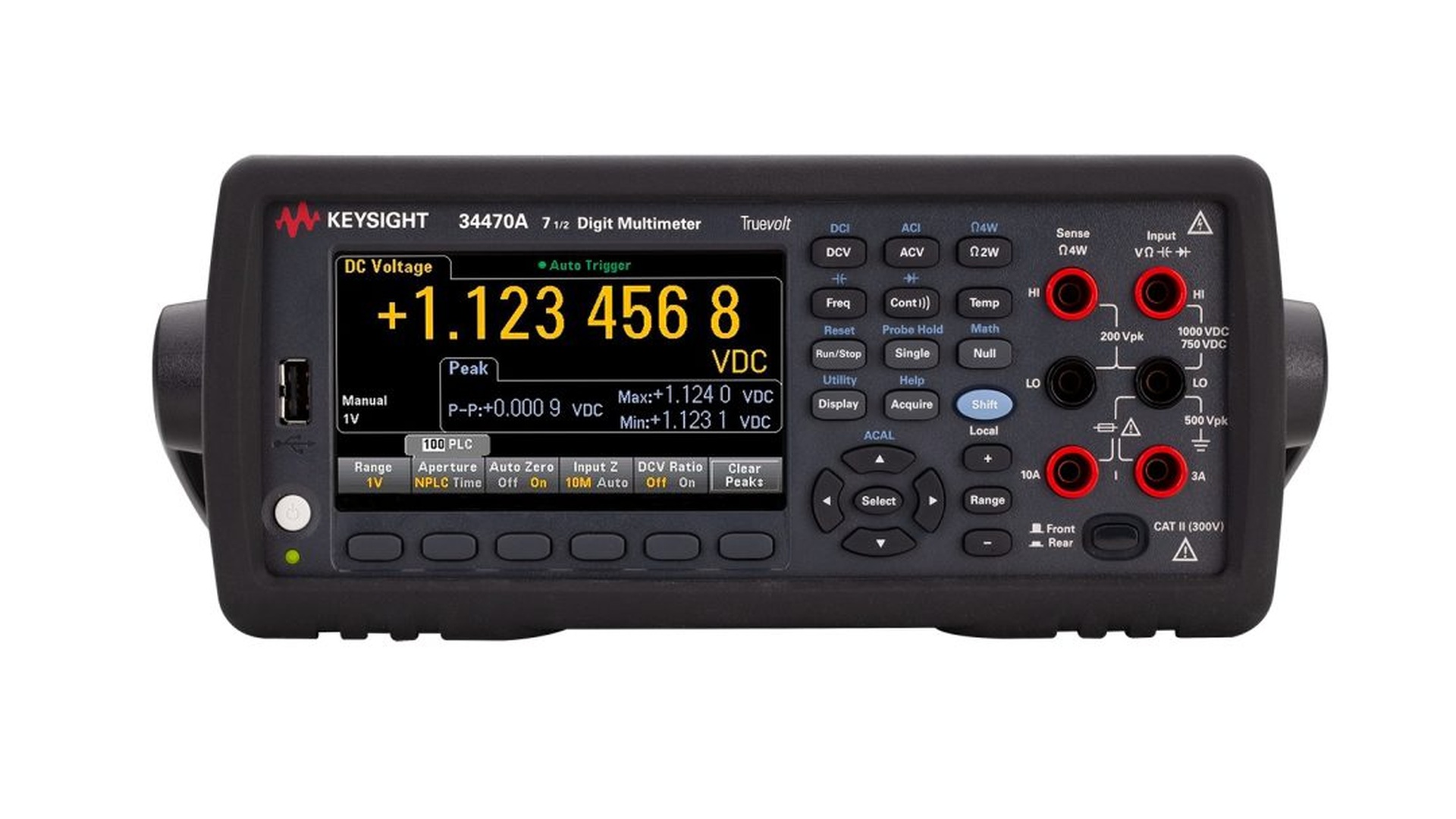
Keysight 34470A
So the multimeter is a companion to a scope, not a replacement. Use it for a number, and the scope for what the number is made of.
Ripple is judged against the rail spec. A 1% tolerance on a 3.3 V rail comes to 33 mV. That 33 mV covers the whole tolerance band, so the ripple allowance shrinks if DC accuracy and transient deviation also draw on it.
An error of a few millivolts can flip a pass into a fail. Match the method and the bandwidth to the spec you are checking.
Why Do Ripple Measurements Come Out Wrong?
Bad readings usually trace to four parts of the setup. The supply, the load and the stray pickup around the bench still have to be checked before the setup takes the blame.
- Probe attenuation. A 10:1 passive probe divides the signal by ten, which cuts the signal-to-noise ratio for small ripple.
- Ground connection. Keysight’s guidance on connecting an oscilloscope to a circuit calls for a short ground to reduce loop area and pickup.
- DC offset. Millivolts of ripple can sit on several volts of DC. Without enough probe or channel offset, raising vertical sensitivity pushes the trace off screen.
- Bandwidth. Too much admits broadband noise. Too little removes real switching harmonics and transients.
Read more: Unsure whether the oscilloscope or the probe is the limit? Our guide on how to choose the right oscilloscope for your engineering work explains bandwidth, sample rate and channel selection.
How Should You Connect the Probe to the Rail?
The connection sets loading, bandwidth and pickup before you touch a front-panel control. Three routes are common: a passive probe, a coaxial link to a 50 ohm input, and a power rail probe.
(A) The 10:1 Passive Probe
A 10:1 passive probe is the one already at hand, and it puts relatively little DC load on the rail. Its attenuation is the problem: it cuts millivolt ripple by ten at the oscilloscope input. A long ground lead adds inductance and picks up switching noise.
It suits a quick check when the ripple sits well above the noise floor. For low-level work, fit a short ground spring, check what the probe itself adds, and weigh the result against the tolerance you need.
(B) The Oscilloscope’s 50 Ohm Input
A coaxial link to the scope’s 50 ohm input gives 1:1 transfer and low connection noise. It also puts a low resistance to ground. The N7020A and N7024A datasheet notes that such an input sinks about 30 mA per volt of supply, which can change how the rail behaves.
There is a second cost. A DC blocking capacitor fixes the offset problem, but it also strips DC information such as supply compression and slow drift.
Use this route only when the rail, the scope input, the cable and the connection are rated for the DC current and power it draws. Do not assume a sensitive rail will take direct 50 ohm termination.
(C) The Power Rail Probe
A power rail probe gives low attenuation, wide offset and light DC loading. The Keysight N7020A offers 2 GHz bandwidth at 1.1:1 attenuation, and the N7024A reaches 6 GHz at 1.3:1. Both present 50 kOhm at DC.
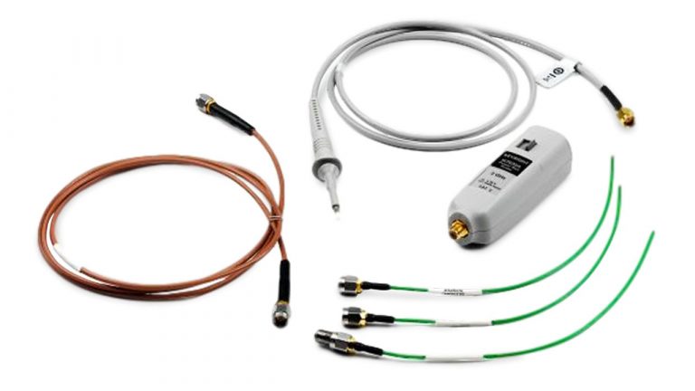
Keysight N7020A
Keysight states that the N7020A adds about 10% to the scope’s baseline noise. Its ±24 V offset range centres a live rail at a sensitive vertical scale, with an active signal range of ±850 mV. The N7024A offsets ±15.25 V.
A Worked Comparison of Loading
Keysight’s own figure makes the loading gap concrete. Take an example 3.3 V rail. Through a 50 ohm path at about 30 mA per volt, the measurement draws roughly 100 mA.
Through the N7020A’s 50 kOhm input the same rail gives up about 66 microamps, since 3.3 V divided by 50,000 ohms is 66 µA, about a thousand times less.
Attenuation shifts visibility just as sharply. An example 30 mV ripple arrives as 3 mV through a 10:1 passive probe. At 1.1:1 the power rail probe keeps almost all of it.
If you are weighing a passive probe, the 50 ohm input or a dedicated probe, share your rail voltage, expected ripple, bandwidth and allowable loading with Tekmark. Our technical engineers can recommend a suitable configuration.
Which Oscilloscope Settings Give a Clean Ripple Reading?
A good connection still needs the right settings. Coupling, bandwidth and acquisition mode should follow the signal content and the spec under test. Four have the largest effect.
(i) Choose AC Coupling or Probe Offset Deliberately
AC coupling inserts a high-pass filter that blocks the DC part, which frees you to raise vertical sensitivity on what remains. Keysight’s note on when to use AC coupling gives power-rail ripple as a common case.
The filter has a cost. It also removes low-frequency drift, droop and recovery behaviour, so DC coupling with enough probe offset is the better choice when that content matters.
Use AC coupling for steady ripple, once you have checked its low-frequency cutoff will not touch what you are measuring. Keep DC coupling for startup, compression, load transients and slow rail movement.
(ii) A Bandwidth Limit to Hold Back High-Frequency Noise
A bandwidth limit cuts broadband noise that would otherwise inflate a peak-to-peak figure. Keysight’s guide on how to use an oscilloscope covers it, and many instruments carry a 20 MHz setting.
Do not switch it on by habit. Match it to the stated measurement bandwidth in the specification, or to what you are trying to see. Open it up when switching spikes and fast transients are the point.
(iii) Averaging or High-Resolution Mode
Averaging reduces uncorrelated noise across repeated, stably triggered acquisitions. High-resolution mode averages neighbouring samples inside one acquisition, which raises effective resolution but lowers measurement bandwidth.
Averaging suits stable periodic ripple and can hide intermittent events. High-resolution mode helps on single captures, as long as its reduced bandwidth still covers the signal.
(iv) A Short Ground to the Same Reference
A short ground return cuts loop inductance and pickup. Ground next to the measurement point and keep the loop small.
Swapping a long alligator lead for a ground spring often gives the clearest single improvement here. Short oscilloscope probes and accessories make that connection easier to get right.
Which Oscilloscope and Probe Should You Use?
The system has to resolve a small AC signal sitting on a much larger DC level. Front-end noise, vertical resolution, offset range and probe loading matter more here than bandwidth alone.
The Keysight InfiniiVision HD3 Series uses a native 14-bit ADC across 200 MHz to 1 GHz configurations.
Keysight states a noise floor as low as 50 microvolts RMS, which supports small-signal visibility when the rest of the setup is right. The Keysight HD304MSO is the four-channel model, and it sits within the wider digital storage oscilloscope range.
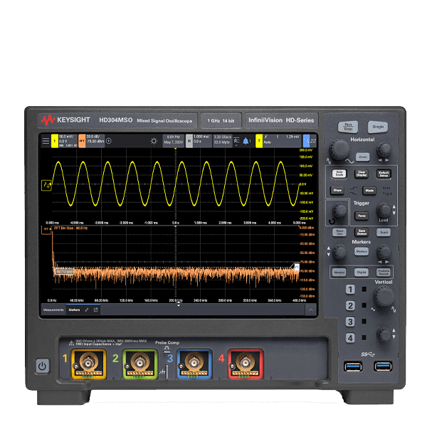
Keysight HD304MSO
On the probe side, the N7020A pairs low attenuation with light DC loading and enough offset for common rails.
Its ±24 V offset and 50 kOhm DC input suit low-level rail measurements. The N7024A trades offset range for bandwidth, reaching 6 GHz for high-frequency transient work.
| Connection method | Attenuation | DC offset handling | Loading on rail | Best suited to |
| 10:1 passive probe | 10:1, reduces ripple at the input | Limited by scope or probe offset | Low DC loading | Quick checks when ripple stays above the noise floor |
| Oscilloscope 50 ohm input | 1:1 | Limited; a blocking capacitor removes DC information | Heavy, about 30 mA per volt | Rated rails that can tolerate the load |
| N7020A / N7024A power rail probe | 1.1:1 / 1.3:1 | ±24 V / ±15.25 V probe offset | 50 kOhm at DC | Millivolt ripple, noise and transients on live rails |
Source: Keysight N7020A and N7024A power rail probe datasheet.
| Instrument | Key specification | Relevance to ripple |
| N7020A power rail probe | 2 GHz, 1.1:1, 50 kOhm at DC, ±24 V offset | Low attenuation and light loading for millivolt rail work |
| N7024A power rail probe | 6 GHz, 1.3:1, 50 kOhm at DC, ±15.25 V offset | More bandwidth for high-frequency noise and transients |
| InfiniiVision HD304MSO | 14-bit ADC, 4 analog channels, 200 MHz to 1 GHz, 50 µVRMS noise floor | Low-noise platform for small-signal measurement |
| 34470A digital multimeter | 7.5-digit, true-RMS AC voltage | A numerical RMS value within specification, with no waveform |
Read more: Working across RF and power on the same bench? Our guide to radio frequency measurement covers the instruments used to separate signal from noise.
What to Confirm Before You Choose a Ripple Measurement Setup
Pick the setup from the rail voltage, the smallest ripple you must see, the bandwidth you need and the loading the rail allows. Settle these five points before you specify anything.
| What to confirm | Why it matters | How to specify it |
| Rail voltage and probe offset | The probe must centre the DC rail without clipping | List each rail voltage, checked against the probe’s offset range |
| Smallest ripple to resolve | Low-level ripple needs enough system signal-to-noise ratio | The minimum RMS and peak-to-peak amplitude |
| Required measurement bandwidth | Ripple, harmonics and transients sit in different frequency ranges | The product test specification, or the fastest event of interest |
| Allowable rail loading | Direct 50 ohm termination can change how the rail behaves | The DC current and power the measurement path may draw |
| Coupling and low-frequency content | AC coupling removes DC and attenuates slow changes | Whether startup, droop, drift or compression must stay visible |
Sources: Keysight power rail probe datasheet and when to use AC coupling.
Conclusion
A power supply ripple measurement misleads when the setup adds noise, cuts the signal, loads the rail or filters out content you needed. The supply’s own behaviour and the operating conditions still have to be checked.
The three failure routes are easy to name. A 10:1 passive probe pushes low-level ripple toward the system noise floor, a direct 50 ohm connection loads the rail, and the wrong coupling or bandwidth hides or exaggerates part of the waveform.
So build the setup around the question. Use a short, low-noise connection, pick coupling and bandwidth from the measurement objective, and confirm the probe and oscilloscope can resolve the expected signal without disturbing the rail.
Why Tekmark?
Tekmark is the authorized Keysight distributor with strategic coverage across Southeast Asia, operating through direct offices in Malaysia, Singapore, and the Philippines.
- Over 30 years of expertise as a regional electronic test and measurement solutions provider
- Established presence across Southeast Asia, supporting customers through an extensive regional network.
- In-house R&D engineering expertise for application support and system integration.
- Value-added services, including calibration, professional training, and technical consultation.
- Dedicated local technical support before, during, and after your purchase.
FAQs
Probe attenuation, a long ground lead, unsuitable coupling or bandwidth, oscilloscope noise and electromagnetic pickup can all distort a reading. The supply and the load conditions should also be checked before the setup takes the blame.
A 10:1 probe cuts millivolt ripple by ten at the oscilloscope input, and a long ground lead picks up interference. It is fine for a quick check. Low-level work needs a short connection and a check that the signal stays above the system noise floor.
A power rail probe measures small ripple, noise and transients on a DC rail. The Keysight N7020A gives 1.1:1 attenuation, 50 kOhm DC input, ±24 V offset and 2 GHz bandwidth. Keysight states that it adds about 10% to the oscilloscope’s baseline noise.
It depends on the measurement. AC coupling removes the DC component and helps with steady switching ripple, but it also suppresses low-frequency content. Use DC coupling with enough offset when startup, droop, compression or slow rail movement must stay visible.
It reduces broadband noise and improves a steady-state reading when it matches the specified test bandwidth. It can also remove real high-frequency spikes and transients. Open the bandwidth up when those events are what you are looking for.
The Keysight 34470A measures true-RMS AC voltage within its specified frequency range and input conditions. It gives a number, but no waveform shape and no reliable view of brief spikes or load transients. Use an oscilloscope when time-domain detail matters.
Related Articles